


SPWM Application and Principle Analysis
Application example: Three-phase two-level bridge inverter
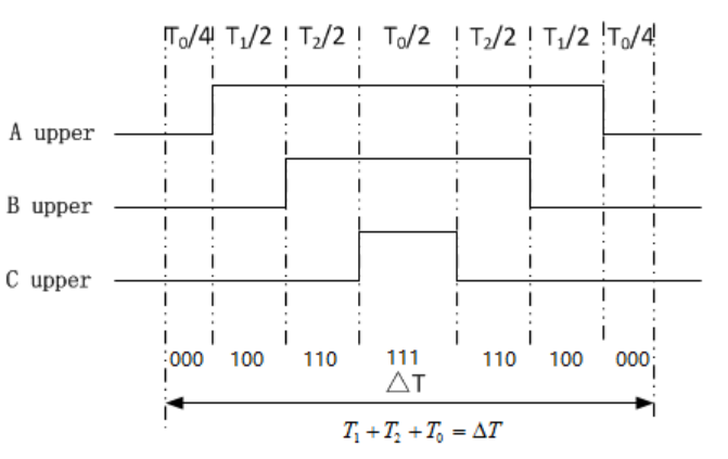
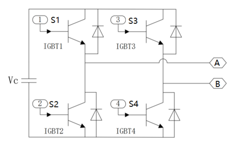
The following figure shows the structure of the two-level bridge SPWM circuit. The circuit adopts the main circuit mode of two-level, three-bridge arm, using IGBT as the on-off element and diodes to construct the bypass circuit, and modulates the pulse control signal of SPWM to control the on and off of the IGBT in the bridge circuit, respectively, to change the topology of the circuit and update the circuit state.
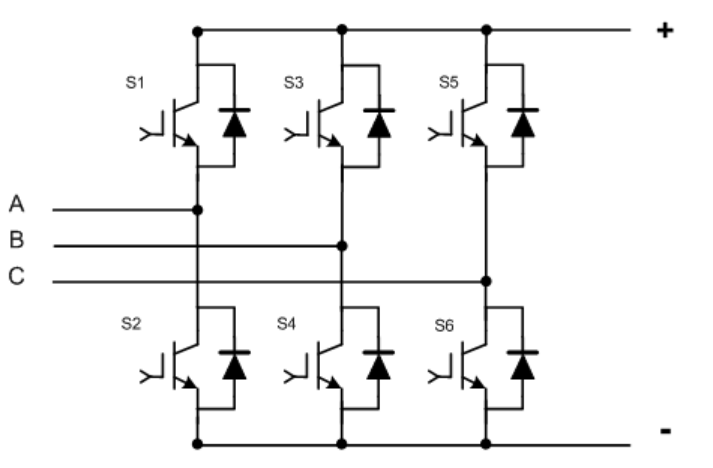
Two level bridge SPWM structure
Basic principle of SPWM modulation:
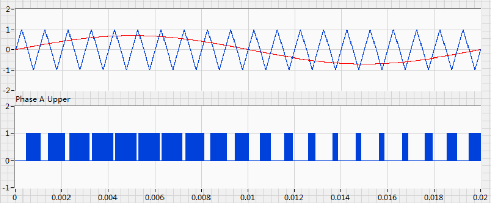
The basic principle of SPWM modulation is to compare the sinusoidal modulating waveform with the triangular carrier waveform:
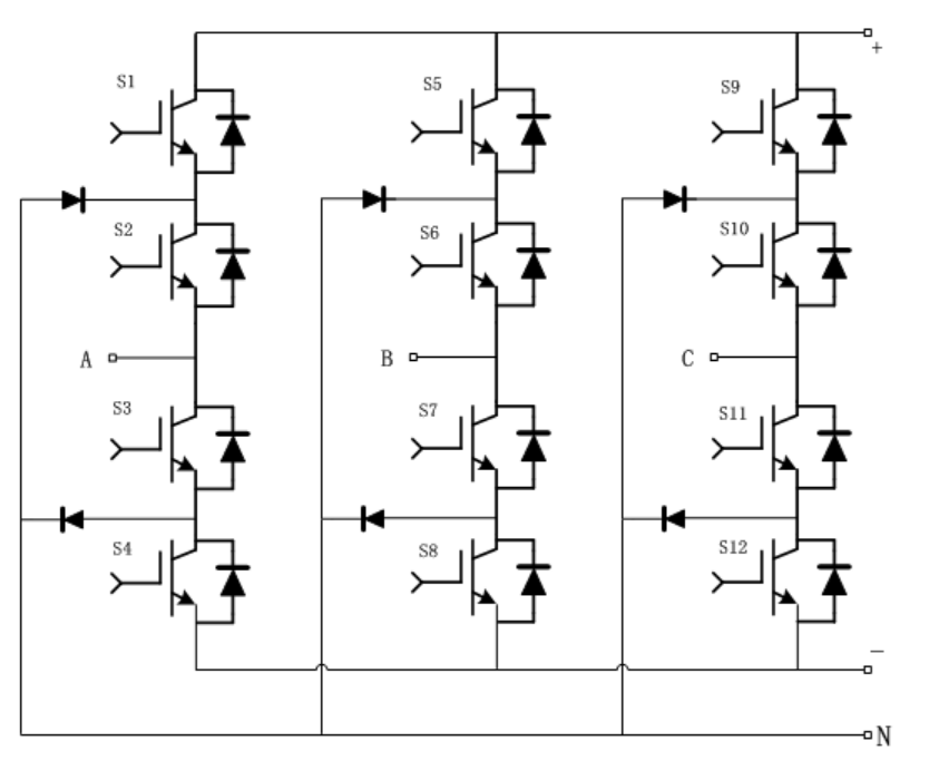
When the sine wave is greater than the triangular wave, a conduction signal is given to the upper bridge arm and a shutdown signal is given to the lower bridge arm;
When the sine wave is smaller than the triangular wave, the upper bridge arm is given the off signal and the lower bridge arm is given the on signal;
In this way, the pulse width can be obtained according to the sinusoidal law and the sine wave equivalent PWM waveform, also known as SPWM (Sinusoidal PWM), the following figure shows how to generate the PWM pulse of the upper bridge arm by comparing the reference waveform with the triangular carrier waveform.
SPWM related concepts
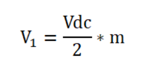
Modulation ratio (m): refers to the ratio of the amplitude of the reference sine wave to the amplitude of the triangular carrier waveform. For SPWM modulation, the amplitude of the base frequency voltage waveform generated by the inverter has the following relationship with the modulation ratio m and the DC voltage Vdc:
DeadTime: For voltage source type inverter circuits, the switching commands of the upper and lower bridge arms are complementary. Since the actual switching devices are not ideal and cannot be switched off instantaneously, in order to avoid simultaneous conduction of the switching devices of the upper and lower bridge arms, the devices are burned. It is necessary to delay the turn-on command of each tube slightly for a certain period of time before issuing it, and this time is also often referred to as the dead time.
SVPWM Principle Explanation
The space vector modulation method, or SVPWM for short, is a very common PWM control method for three-phase voltage source converters. Compared with SPWM, SVPWM can effectively improve the DC bus voltage utilisation, reduce the harmonic rate of the AC side voltage and so on. However, SVPWM requires more calculations.
SVPWM basic principle:
Consider the reference sinusoidal voltage signal as a rotation vector.
When the upper bridge arm is on the lower bridge arm is off, the state is marked as 1. For a three-phase voltage source converter, there are eight switching vectors, i.e., (000), (100), (110), (010), (011), (001), (101), (111).
Six vectors (100), (110), (010), (011), (001), (101) divide the space plane into six sectors. A reference voltage vector can be viewed as a linear superposition of two neighbouring switching vectors.
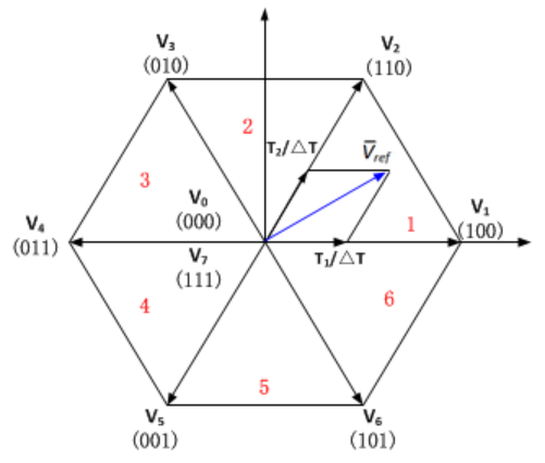
When the reference vector falls on sector 1:
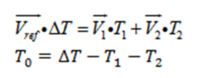
V1 represents vector (100); V2 represents vector (110);
The upper bridge arm switching state is described as follows:
NPC Three Level Bridge PWM Pulse Generation
Application example: NPC-type three-level bridge converter
The classic NPC-type three-level bridge converter, whose circuit consists of the same IGBT module with the addition of a clamp diode, is modelled as shown in the figure above. During operation, according to the polarity of the voltage and the polarity of the current, combined with the control strategy, the action of the IGBT switch is controlled to achieve the operating requirements of the converter.
Basic principles of PWM modulation:
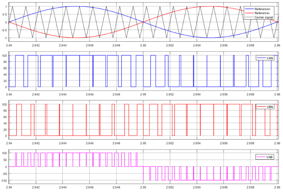
The pulse generation method of PWM commonly used in NPC-type three-level bridges is Phase-Disposition SPWM.
For the NPC-type converter, taking phase A as an example, the two IGBT switching modes of S1 and S3 are complementary, and the two IGBT switching modes of S2 and S4 are complementary. In order to achieve the control requirements, it is necessary to translate the triangular wave corresponding to the two sets of switches up and down and compare them with the same reference wave to generate the switching signals that control the IGBT action. The specific working method is as follows:
In this way, a PWM waveform can be obtained that varies in pulse width according to a sinusoidal pattern and is equivalent to a sine wave, as shown in the following figure.
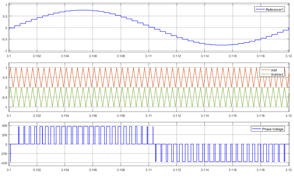
H-bridge unipolar pulse generation
Application example: H-bridge converter unipolar pulse generation
The following figure shows the structure of an H-bridge converter. The H-bridge can be interpreted as a superposition of two half-bridges, S1 and S2 as a group, and S3 and S4 as a group.
VPN = +Vc when S1 and S4 are conducting and S2 and S3 are blocking;
VPN = -Vc when S2 and S3 conduct and S1 and S4 block;
VPN=0 when S1 and S3 are on and S4 and S2 are blocked (S4 and S2 are on and S1 and S3 are blocked).
In order to achieve the above three operating states, the control strategy for each IGBT of the H-bridge is in accordance with the right-hand side of the figure below. That is, the reference waveform is inverted, compared with the same triangular waveform, and the on-off signals are delivered to S1, S2, S3, and S4, respectively, to achieve the control requirements.
Compared with the half-bridge converter, the H-bridge converter has a higher utilisation of the DC bus voltage, and can output the peak AC waveform Vpeak=Vc, but at the same time, the number of IGBT switches required is increased by a factor of one compared with the half-bridge converter.
The principle of operation is shown in the figure below:
Phase Shift PWM
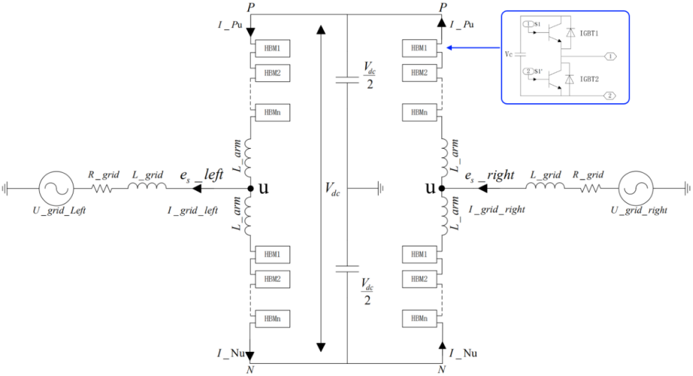
Application example: Single-phase MMC back-to-back topology
In recent years, with the introduction and common application of MMC structure, Phase Shifted PWM (PS-PWM) has started to become a necessary PWM modulation method. Due to the large number of switching devices and the complexity of the control logic in MMC structures, the application of SVPWM in MMC structures has shown obvious shortcomings compared to PSPWM. For example, the logic is complex, the calculation is large, and the controller requirements are high.
The following figure shows the back-to-back structure of a single-phase MMC. As can be seen from the figure, each MMC has the same number of sub-modules on the upper and lower bridge arms, which are connected together by cascading. From the structure of the sub-modules, it can be seen that each sub-module can output a voltage V = Vc or 0.
Fundamentals of PS-PWM modulation:
From the SPWM presented above, it is clear that for the modulation of a single sub-module, two levels, Vc and 0, can be obtained. In order for the overall MMC structure to work properly and get the desired sinusoidal voltage waveform, the sub-modules of the same bridge arm of the MMC need to be controlled according to phase-shifted PWM.
The 5-level MMC has four sub-modules in one bridge wall; as shown in the PSPWM modulation method, there are four triangular waves, each of which has a phase difference of 90 degrees; each sub-module corresponds to a triangular wave; these four sub-modules correspond to the same reference wave, and the comparison between the reference wave and the corresponding triangular wave goes to the control of the switching on and switching off of IGBTs of the sub-modules, which ultimately produces the stepped sinusoidal-like voltage waveforms.