


Applicability of Hardware-In-the-Loop (HIL) Products
With the increase in circuit structure complexity and the increase in the number of switches, in the process of R&D and testing of controllers with high power, complex systems and high test requirements, compared with the traditional physical test method, the hardware-in-the-loop (HIL) method is used for R&D and testing, which is faster, more efficient, and safer to experiment, which can greatly save the cost of the controller R&D and testing.
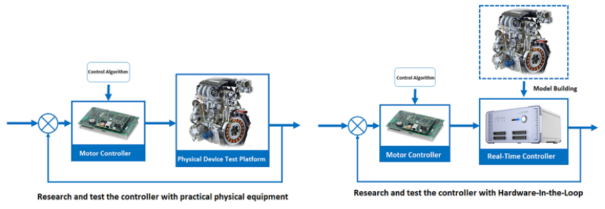
As shown in the above figure, the hardware-in-the-loop test uses a simulator to accurately and real-time simulate the operating characteristics of the system circuit and sensor signal output, and it can be connected with all the IO signals of the controller to test. The hardware-in-the-loop platform can create a signal-level system simulation and real-time response test environment for the controller to be tested before the physical hardware test platform is integrated.
Five Core Indicators of HIL Products
Currently, the relevant HIL products on the market are mainly European and American brands, and Shanghai Modeling-tech Energy Technology Co., Ltd is currently the only independent brand company that can benchmark imported products in terms of small step simulation. Although there are not many brands of simulation products in the world, how should users choose suitable HIL products and what key indicators of HIL products should be paid attention to? The following editor will introduce the five core indicators that need to be paid attention to when evaluating HIL products from two aspects: functionality and applicability.
Functional Indicator1: Simulation Step
The core indicator of the hardware-in-the-loop (HIL) simulation platform is the simulation step. For the hardware-in-the-loop simulation (HIL) of power and power electronic systems, the time scale (simulation step) of real-time simulation is a very important concept. The real-time simulation of power and power electronic systems can be divided into the following two categories according to the simulation step:
-
Large step simulation: Based on multi-core CPU, simulation step (25-100us), suitable for AC power grid system;
-
Small step simulation: Based on FPGA, the simulation step is small (0.25-1.25μs), suitable for power electronic systems;

-
If the user pays attention to the overall characteristics of the system operation, such as researching the power frequency AC part of the operating system, verifying the EMS control strategy of the microgrid system, and researching the energy dispatching of the circuit operation, this type of application focuses on the upper-level dispatching operation. The algorithm and the characteristics of the system as a whole, the circuit model does not have high requirements for the simulation step when performing real-time simulation. At this time, it is more appropriate to choose a large step simulation based on the CPU;
-
If the user focuses on the inverter-level operating characteristics, such as verifying the control algorithm of the inverter, paying attention to the operating characteristics of a single switch, paying attention to detailed waveforms such as high-frequency harmonic components, etc., In order to better simulate the operation of power electronic switches, the frequency of the simulator must be at least 50-100 times the frequency of the PWM control signal. This means that the simulation step must be at least 1μs or less. At this time, only FPGA-based small step simulation technology can meet the requirements of application.
Note: This data is generally a step size indicator at the minimum circuit size, and simulation step size testing should still be based on the circuit size that will be loaded during use during evaluation.
Functional Indicator2: Methods to support model building
When evaluating HIL products, the Methods to support model building is also a more important performance indicator, which determines whether users can freely build the circuit topology they want to simulate. Some HIL products support users to build arbitrary system topologies, and also support users to model circuits based on single components. They are flexible and suitable for users who require high topology changes, research new topology, or are concerned about the operating characteristics of a single switch; some HIL products will provide users with a model library, which supports limited model topology in the library, and cannot support users to freely build models. The flexibility is limited, and it is suitable for users with relatively fixed research objects.
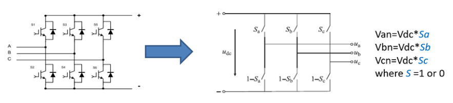
Why are the models supported by different products different? This is related to the modeling method. Taking the two-level bridge that users are more familiar with as an example, there are three modeling methods based on switching function modeling , average value modeling and detailed modeling based on L/C switch.
-
Switch Function Modeling
Switch function modeling Based on the power electronic topology, the switching function modeling method lists its basic equations, introduces switching functions, and realizes the modeling of power electronic devices. The switching function modeling is suitable for fast offline simulation and small step real-time simulation. But the switching function modeling needs to know the circuit topology in advance, does not support the modeling of any topology, and is not suitable for any working conditions, it is difficult to simulate the situation of uncontrolled rectification.
-
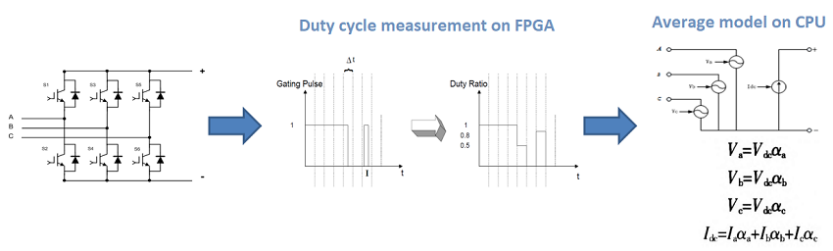
Average Value Modeling
The modeling method of average value modeling is based on the switching function method, combined with the FPGA hardware to measure the duty cycle of the PWM wave, and the model is run in real time on the CPU with a larger simulation step (large step means Real-time computing requirements are reduced). In use, the average value modeling also needs to know the circuit topology in advance, does not support the modeling of any topology, and cannot simulate any operating conditions based on a single switch; At the same time, because the step size is relatively large, some simulation details will be lost, so it is generally used in the simulation of large-scale system based on CPU.
-
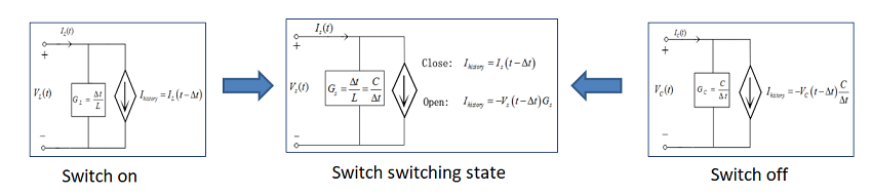
Detailed Modeling Based on L/C Switch
The detailed modeling based on L/C switch is based on the model simulation of a single switch, and the method of L/C switch modeling is adopted, that is, when the switch is closed, it is modeled as a small inductance, and when the switch is open, it is modeled as a Very small capacitance. In this way, the switches in the circuit will not affect the parameters of the circuit topology when the state is switched, and the accuracy of the simulation can be effectively improved. At the same time, the model simulation method based on a single switch supports users to build any power electronic topology, and can also simulate the operating conditions of any switch independent operation in the analog topology. It is the mainstream method of power electronic system switch modeling at present.
Functional Indicator3: Simulation Scale
Another key indicator of the hardware-in-the-loop (HIL) simulation platform is the simulation scale of the system. The evaluation of the simulation scale not only needs to consider the operation of a single simulator, but also evaluate whether there is the scalability of parallel operation of multiple simulators.
If you want to research CPU-based real-time simulation with a relatively large time scale and a relatively large system scale, the scale of the system simulation is determined by the capacity of the single-core CPU and the number of CPU cores of the simulator. For some complex situations of the power system, multiple simulators are even required to perform joint simulations in parallel to increase the scale of simulation operations;
If you want to research a small step simulation application that requires a small simulation step, the number of switches and the simulation accuracy, the simulation scale of the simulator is determined by the resources of a single FPGA chip and the number of FPGAs. If the researched system is relatively small, a single emulator or even part of the FPGA capacity of a single simulation can meet the requirements; if the researched system is relatively large and the number of switches is very large, It is necessary to perform FPGA co-simulation through multiple simulators in parallel, thereby increasing the number of switching elements that can be simulated.
Usability Indicator1: Model Compatibility
The hardware-in-the-loop (HIL) simulation platform supports the model in two ways:
1. Support mainstream modeling and simulation software, such as Simulink, suitable for users who mainly use Simulink for algorithm development or system research, and can easily migrate offline simulation models to the HIL simulation platform;
2. The simulation platform uses a specific model editing environment, which increases the time cost of re-modeling for users who use other modeling environments. It also brings inconsistencies in the numerical results of the two modeling environments. Therefore, it is suitable for non- Simulink users or users who have professional industrial model library usage requirements.
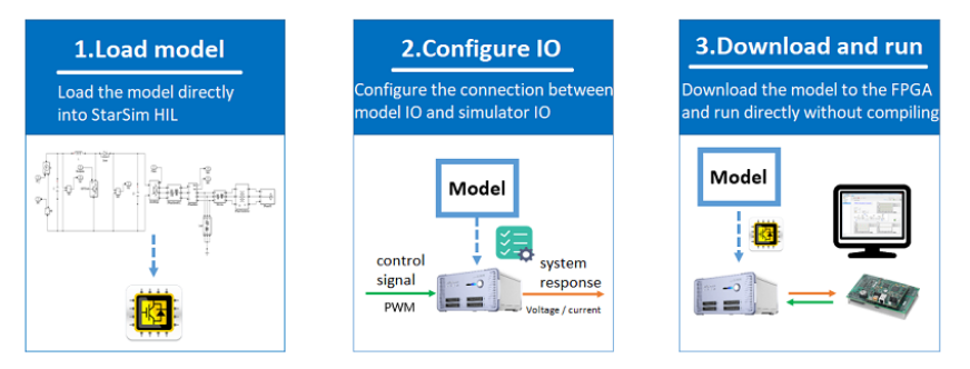
Usability Indicator2: Usage Mode
Load the mathematical model into the hardware-in-the-loop (HIL) simulation platform, and different products have different usage mode. The common method is to compile the mathematical model and then deploy it to the real-time simulator. This method requires waiting for recompilation after each circuit modification, and the compilation errors will occur, which is time-consuming. The small step real-time simulation technology of Modeling-tech Energy supports directly loading the circuit model into the FPGA chip of the simulator, and directly evaluates the resources consumed by the simulation scale without compiling, which can save a lot of compilation and loading time in the application scenario where the circuit needs to be changed repeatedly.
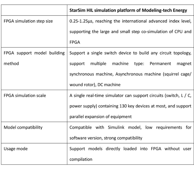
HIL Products of Modeling-tech Energy
In the previous article, we mentioned that the step size of power electronic system simulation is generally on the order of 1us(equivalent to one million updates per second), which is very challenging for the realization of real-time simulation. The StarSim HIL real-time simulation product independently developed by Modeling-tech Energy utilizes the powerful parallel computing capabilities of FPGA to perform small step simulation with an accuracy of up to 250ns, accurately simulates the operating characteristics of power electronic switches, and reaches international advanced technical indicators. At the same time, although high-end FPGA hardware is used in real-time simulator, the real-time simulation software of StarSim HIL can easily complete the combination of user model and FPGA chip without any programming work by the user.
Modeling-tech Energy provides domestic leading and internationally advanced FPGA-based hardware-in-the-loop simulation solutions that can meet the diversified demands of users. Compared with imported products, the StarSim HIL platform of Modeling-tech Energy has more advantages in usability, customization, and product services.